The purpose of the Transmission Tech Page is to provide free accurate information pertaining to GM automatic transmissions. The tech page will grow to be several articles about specific units and the specific mods and the reasons to do those mods. Visit often for updates.
Transmission FAQ
How much fluid does my transmission hold?
This question is hard to accurately answer. It varies due to converter size, pan depth, cooler and line size, fresh build or service, and other variables.
Our suggestion is to ensure your dipstick is correctly marked, add approx 1/2 qt of fluid to the converter before install, with some fluid spread on the converter hub to prevent the seal or pump bushing from being dry. Add 4 qts on most units after install, start the engine, and then add 3-4 qts and start checking the level.
A Powerglide, TH350, or stock TH400 may be full with 9-10 qts on a fresh install, or in some cases it may take 15 qts.
How do I know that the dipstick is reading correctly?
The fluid level should be even with the pan gasket when warm, idling in park or neutral. You can confirm this level on a dipstick before install, or once it is installed, you can loosen the pan slightly to let excess fluid drain, tighten the pan back up, clean the dipstick, re-insert and check, and then mark the indicator at the proper level.
How do I know the converter is completely seated?
The old “3 clicks” method is not an accurate way to determine if the converter is correctly installed. There MUST be clearance between the converter and flexplate when the trans is bolted to the engine. In a perfect world this would be 1/8″ or .125″ everytime, and you just bolt it up and go. In the real world, we have to check it and make adjustments as necessary.
On a typical GM engine, the flexplate mounting pads are 1″ away from the bellhousing flange area of the block. The converter pads when seated completely will be approximately 1 and 1/8th inch ( 1.125″)recessed into the bellhousing. Seat the converter, then measure the distance from the engine block bellhousing mating flange, to the mounting pad on the flexplate.
Then do the same from the transmission bellhousing mating face, to the converter mounting pads. You should have the converter sitting deeper than the flexplate protrudes from the engine. If so, you can now bolt the transmission to the engine. With the trans bolted to the engine, you should be able to turn the converter freely. Check the distance from the converter to the flexplate with the converter completely seated into the transmission. You should have 1/8″ to 3/16″ clearance. (.125″-.187″) If it is more than 3/16″, you should use flat ground washers to shim between the flexplate and converter.
Transmission Failures
There are many reasons for automatic transmission failures. I’m going to discuss these to help enthusiasts understand them and hopefully prevent them.
Low Fluid Level
As a builder we see evidence of this way more often than most would think. How do we know its low fluid level? Because the conditions inside the transmission will be the same as low pressure since low pressure is the result of low fluid level. One quick indicator is the condition of the forward driving clutch. In most transmissions this is a non shifting clutch and has plenty of capacity. If the forward clutch frictions are failed or showing signs of distress, and there isn’t a pump failure or anything damaged in the circuit (sealing rings, lip seals), it’s a good indicator that the fluid level may have been low. If the 2nd gear friction element also shows damage, but the rest are in good shape, it is further confirmation.
We’ve seen experienced shops damage transmissions because of low fluid level. I don’t believe this is done on purpose. I believe it to simply be a combination of poorly made parts (dipsticks), lack of knowledge of how to check the accuracy of the dipstick, and in some case being in a hurry or not fully completing a proper fill. A proper fill includes a short test drive with each gear change being made, and THEN final fluid level check.
However the fluid level check cannot be properly performed unless the dipstick measures correctly. Which needs to be done BEFORE the transmission is installed or by other methods that we’ll discuss.
- Check the accuracy of the dipstick.
- Add 4-6 qts of fluid before starting a new install.
- Start engine and begin filling while checking the dipstick.
- When the full level is reached, make a short low throttle test drive to go through each gear manually and automatically to ensure function.
- Recheck the fluid level and add as necessary after test drive. Check for leaks.
- Failure to complete any of the above steps may result in transmission failure. It is unreasonable to expect a hydraulically operated piece of equipment to have low fluid and live. Although it is a simple thing it is critically important.
Shifter Adjustment
Shifter adjustment is another often overlooked and important step to success when dealing with an automatic transmission. Some transmissions are more sensitive than others to the adjustment or lack of before it has any adverse effect.
Each range MUST line up between the shifter and the transmission detents. Some shifters don’t have detents and simply rely on the transmissions internal detents. However most racing type shifters must have detents to give the positive shifting and control to prevent unwanted shifts. It is most important that the range selected for most driving is PERFECTLY adjusted, but if the other ranges are not also perfectly adjusted, anytime you select them, you could be causing an internal pressure leak, which can cause failure. This is an installer’s responsibility, no matter how well built the transmission is, it cannot overcome faulty shifter cable adjustment.
Converter Installation and Spacing
This is a very common cause of pump damage and ultimately transmission failure. It is also easy to detect on teardown. The pump gear or rotor has “ears”, “tangs”, or “flats” that mate with the converter drive hub. If the converter is roughly installed, or forced in while bolting the transmission to the engine, the pump gear or rotor will show damage, to the mating area and will often be cracked.
The converter drive hub will also usually have damage and can be cracked. If the engine is started with an improperly installed converter the gear/rotor will grind into the rear cover. Many times the transmission case will also suffer from a broken bolt hole area when this occurs depending on how evenly the bolts are tightened.
There is a common misconception that there needs to be a certain number of “clicks” when installing a converter. This is false. The converter must mate with the stator shaft, input shaft, and pump gear/rotor. The proper way to detect if the converter is completely installed is to measure it’s depth from the bellhousing mating flange. This requires a straight edge across the front of the bellhousing and measuring to the converter mounting area. On most GM rear wheel drive transmissions this will be between 1” and 1 1/8th “.
It is a good idea to check the converter fitment to the flexplate before installing the transmission. You want to check that the bolt holes line up, the converter pilot fits into the crankshaft or adapter, and the converter sits flush against the flexplate.
Once the transmission is in place but before completely tightening the bellhousing bolts, free rotation of the converter needs to be verified to ensure it didn’t move while jacking it into place. Tighten the bellhousing bolts and confirm again. If at any time the converter doesn’t spin, it needs to be removed, the transmission pump removed, disassembled, and inspected for damage.
Once bolted up, with the converter completely seated in the pump, it should have 1/8th” to 3/16” (.125 – .187”) of clearance between the mounting pads and flexplate. Many aftermarket flexplates may not be exactly the same as the OEM parts. There is also an allowance on the build height of the converter. If the clearance is too small, it will not allow expansion or movement of parts. If it is too great, you can use flat ground washers of equal thickness as spacers. Be sure that this doesn’t result in the converter pilot not being centered in the rear of the crankshaft or spacer.
Line Pressure Control and Rise Systems
These systems include vacuum modulators, TV cables, and electronic pressure control solenoids (EPC or PCS).
A vacuum modulator is a simple system that defaults to max line pressure when unhooked. The max line pressure can cause problems if the transmission isn’t modified for it. However this is an almost foolproof system that many builders have adapted in electronic controlled systems to prevent tuning caused failures.
TV cable operated transmissions are another type of system that works fairly well when the installer FULLY understands the system, the geometry involved, and is willing to be sure it all works properly. A pressure gauge is a fundamental tool to check the function of this system and is helpful on all transmissions.
Electronically controlled pressure systems work well when properly tuned. The pressure control solenoids have proven very reliable and repeatable. Most issues with these system arise from a misunderstanding of the control system that tells the solenoid what to do. These systems are almost always defaulted to max pressure when voltage is not present, to prevent failure in the case that there is a loss of power to the transmission. GM units work off amperage. One full amp or 1.0 commanded amps equals minimal line pressure. Zero amps or a commanded 0.1 amp is maximum line pressure.
The actual pressure is determined by the pressure regulator system in the transmission and how the builder set it up.
The single most important thing that needs to happen on any transmission install is that a pressure gauge needs to be installed and pressures confirmed. The pressure gauge will confirm that the transmission is making proper pressure. Most reputable performance shops are using a transmission dyno to check for proper pressure after the build. It is a good idea for the installer/tuner to check for the desired pressures when dealing with a TV operated or EPC system.
We have seen failures from improper tuning and faulty controllers. These can be difficult for the builder to determine the actual cause because the transmission will pass dyno testing, come back failed, and show all the typical symptoms of low line pressure. After repair, it will pass dyno with good pressure again. If the cause isn’t found by the installer, it will fail again.
Some installers seem to think it is not their responsibility to check line pressure. A pressure gauge is a fundamental tool that should be installed on every new build and install to confirm proper function. It provides a huge amount of data. It will confirm proper build and pump pressure, it will confirm fluid level while accelerating, it will show issues with shifter adjustment, and it will show pressure rise related to the control system.
One of the first questions you will get from any knowledgeable builder will relate to pressure and for help diagnosing transmission issues from any builder, he/she will need data that will most likely involve pressure readings.
The diagnostic process for an automatic transmission goes in a logical order:
- Check fluid level
- Check shifter adjustment
- Check modulator/TV system hookup and adjustment
- Check pressure
Control Systems
Another issue we deal with on many installs is electrical or control issues. Other than the previously mentioned pressure control portion, many of these issues won’t cause immediate failure but they will cause shifting or operation issues. Modern transmissions are unlike a completely hydraulically operated unit such as a Powerglide or TH400. They rely on solenoids to shift, lockup the torque converter clutch, pressure control, and have internal sensors for pressure and temperature. If any part of this system doesn’t work or doesn’t communicate, it can cause problems. Further complicating the issue is that the transmission control is often integrated with the engine control system, so engine codes or problems can cause transmission concerns. These systems get more and more complex and can be challenging for a professional technician to keep up with.
Sometimes diagnosis is simple because a certain set of symptoms indicates an exact cause. Other times it can be difficult to diagnose and may require more complex equipment such as a scanner, digital volt meter, or shift box. When issues arise, it is almost impossible to diagnose an electrically operated transmission without access to the proper tools. This is another challenge of supplying transmissions to customers for installation and why using a local builder or professional installer is often a good choice, especially when dealing with modern transmissions.
The ability to check wiring and see what the controller is doing is a must if you are installing an electronically controlled transmission. You need to have access to a QUALITY scanner or tuning/scanning program. Something along the lines of a Snap-On Solus or Modus, or HPTuners or EFILive. You must also be able to use a digital voltmeter (DVOM). If you do not have these tools and know how to use them, you are not going to have much success diagnosing any issues on a modern powertrain. It is an integral part of owning a modern performance car or truck. The reality is that many installers do not have these tools or know how to use them. The result is that they are incapable of diagnosing the issue or even giving any real data to the builder to help diagnose any problems. If the builder gets the transmission back, puts it on the dyno and it works perfect, or tears it down, finds nothing wrong, and then successfully dyno’s it, the problem is most likely elsewhere.
It is important for the customer to understand that the proper operation of an electronic transmission doesn’t only rely on the proper build, and normal installation concerns of any automatic transmission, but also the control system. The transmission does what it is told by the controller. Tuning shift points, ensuring proper commanded line rise, and torque converter lockup, is out of the builder’s control. It requires cooperation to ensure success. In many cases, the transmission is sourced from one vendor, the tuning from another, and the installation is done by the enthusiast. There are many opportunities for error and sometimes no easy diagnosis or solution. Using a trusted and reputable vendor and following their advice is important.
We dyno test our transmissions for proper pressure, function in all gears with load, proper shifts (firmness), converter charge pressure and flow, any leaks from the front seal, and unusual noises. When we do this we have a good indicator that it will go in the customer’s car and function fine assuming it is properly installed. We do occasionally have failures that slip by the dyno, or are just an unusual “it happens” failure. However most of the failures we see are caused by improper installation and sometimes operation.
TV Cable Set Info
Everybody has heard about the importance of properly setting up the TV cable to ensure you don’t damage your GM overdrive transmission. This is absolutely true and it IS an important step in properly installing your overdrive transmission. Our goal is to ensure you can make this happen with minimal hassle. We’ve helped hundreds of enthusiasts do this successfully.
While it is important it is NOT rocket science. The transmissions that use the TV systems started in the mid 70’s and have been obsolete in OEM vehicles for over 15 years. The average hotrodder can easily accomplish this task either by using commercially available parts or by using their fabrication skills and ingenuity and in some cases even some stock parts.
We’ll talk about some critical steps to doing this:
- Proper TV cable adjustment. This is simple. You are ideally looking for the TV plunger to be fully “depressed” into the valve body. Depending on the calibration of the TV plunger spring and the transmission hydraulics you may not need to be completely depressed but in all cases you should be very near it.
- Proper TV geometry at the throttle linkaqe. This is the most often overlooked step to getting the TV cable properly setup. It’s relatively simple to check though and in many cases is an easy fix.
These two things are what must be correct. Now we will show you how.
Adjusting the TV cable is a pretty simple procedure. If you hold the carburetor or throttle body at WOT (or better yet have a helper do so) you want to activate the release on the cable. These are a button type as used by GM on the cables we use at Jake’s Performance. Some use a clip that must be pried “out” of the cable and then pressed back in to lock the cable adjustment. In either case, unlock the cable adjustment and pull the cable sheath AWAY from the carburetor but towards the transmission or rear of vehicle. You want the wire portion of the cable to be tight with no slack. Lock the release now. Verify that the cable is tight while the throttle is still held wide open (with the engine not running!).
Let the throttle return to the idle position. Feel the wire portion of the cable. It will usually still have some tension, it will always have tension while the engine is running. This is your baseline TV cable setting. It should be very close. You will not have any further adjustment to tighten it. You CAN however slightly loosen it if the shifts are late and hard indicating high line pressure. One thing we’ll mention, all TV cable brackets need to be rigid and not flex during normal throttle operation.
Now, we’ve covered the basic TV cable adjustment. We HIGHLY recommend using a transmission pressure gauge to ensure proper adjustment and transmission pressures. What you are looking for on a gauge is instant pressure rise anytime the TV cable is moved. Particularly from the idle position. The average GM overdrive transmission will have 65-90 psi line pressure at idle on a gauge. This should spike with slight pressure applied on the cable or if the throttle is cracked at all.
Note: Pressures above 90 psi at idle may result in 2nd gear starts, particularly when the transmission fluid is warm. You may need to back off the cable adjustment slightly until you get down to 90 psi or less idle pressure. As long as you have instant pressure rise on any movement of the TV cable, you will not cause damage to the transmission.
As stated earlier the TV cable geometry at the throttle linkage is often overlooked. In many cases an installed is replacing a TH350 that uses a kickdown cable and not a TV cable with their new overdrive trans and since the brackets for the TH350 kickdown cable work with the TV cable and the carb already has a stud on it, they mistakenly assume they can just hook it up, adjust it, and go.
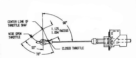
The issue here is that the geometry on the carb linkage is not correct. It has a different radius of arc than what is needed for the TV cable. The TV cable needs a 1.093-1.125″ measurement, the older TH350 kickdown is closer to 1.375″.
This creates a condition where the cable is adjusted correctly but since the geometry is wrong, the overdrive transmission has correct pressures at WOT, but becomes farther away from correct with every degree of throttle less than WOT.
Not really an issue at WOT or even 3/4 throttle.
It becomes an issue just off idle, where a street car operates more often than any other throttle angle. What the pressure gauge will show you is little or no pressure spike on very slight throttle movement. This is the killer of automatic overdrives in retrofit applications. The radius is a simple measurement that can be done with a caliper, a machinist rule, or even in a pinch a tape measure to get an idea. You measure from the centerline of the throttle shaft to the center of the TV stud. It should be approx 1 and 1/8th inch or slightly less. We prefer to see if on the short side. 1.100″.
You also want to see the TV stud rearward of center approximately 20-30 degrees. The OEM spec was 23* but this is not all that critical. It does have some effect on the rate of initial pull of the cable but a properly calibrated performance overdrive transmission will not be overly sensitive.
A picture is provided here to clarify the geometry.
The importance of having proper pressure rise off idle cannot be overstated. A pressure gauge is an invaluable tool for checking this. It isn’t mandatory but it is a time saver and in some cases a transmission saver.
The reason it is so important to have instant pressure rise off idle is because every time you accelerate from a stop, you transition from idle, no load, and low pressure to off idle, accelerating load PLUS torque converter multiplication, and hopefully more pressure.
A torque converter multiplies torque from the engine to the transmission input shaft. Maximum torque multiplication occurs at stall speed. Basically as your car is leaving the stop light. A moderate V8 street engine is making decent torque just off idle, even if only 100 lb/ft, this is multiplied to 200-250 lb/ft to the input shaft. The clutches will not clamp under power without proper pressure. If they slip slightly every time you accelerate from a stop, over a couple of thousand miles they fail.
All you need is proper geometry at the carb linkage and proper TV cable adjustment for a happy overdrive transmission.
If you confirm it with a gauge, you KNOW it is correct.
Approximate pressures you want to see are posted below:
| Gear | Idle or Min TV | Full TV |
|---|---|---|
| P | 70-90 psi | 230-275 psi |
| R | 230-300 psi | 230-300 psi |
| N | 75-90 psi | 230-275 psi |
| 4 | 75-90 psi | 230-275 psi |
| 3 | 75-90 psi | 230-275 psi |
| 2 | 230+ psi | 230+ psi |
| 1 | 230+ psi | 230+ psi |
TH400/4L80 Band Adjustment


The servo bore seen here has a sealing surface for the o-ring on the servo piston. The lip shown in red is the beginning of the sealing surface. This is where you want the piston to be and allow rotation of the output shaft in both directions. (Note: It will be easier to turn one way than the other). You want minimal travel from this point to apply the band. Preferably less than .100” of servo travel by hand. This prevents loss of reverse as the band wears. Use a longer/shorter pin or weld to lengthen the pin and grind to shorten.